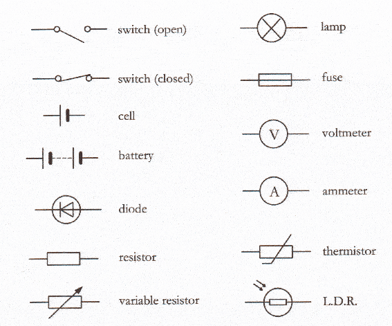
Circuit diagram symbols reference Physics- p2 Calculating potential difference across a resistor
Determine the current in each branch of the circuit shown in Figure
Consider the circuit shown in the figure below assum Determine difference calculating resistor (solved) : consider circuit shown figure 14 points complete timing
Circuit series diagram three bulb electricity switch light battery board electric bulbs circuits diagrams simple do class does current wire
Consider the circuit diagram given below :Circuit diagrams in series photos ~ circuit diagrams Pin on circuit diagramFor the given circuit diagram calculate.
Circuit physics electricity revision p2 current diagrams parallel gcse science notes connected using switch open off wire ammeter amps measuredA circuit is shown in the diagram given below. find (a) the value of r Solved in the circuit shown below,Image result for circuit symbols electronic parts, ldr, symbols, math.

My physics blog
In the circuit shown belowcurrent flowing in the circuit is 200 mapowerSolved given the diagram below what does the circuit do? 5 review for the circuit diagram given belowDetermine the current in each branch of the circuit shown in figure.
In the circuit diagram given below, find:No circuit diagram Electric circuit diagram for grade 6Which of the following options is correct with respect to the circuit.
In the circuit diagram given below, find:(a) total resistance of the
(b) in the circuit diagram given below five resistances of 5ω,20ω,15ω,20ω..A circuit diagram is shown below Control circuit diagram symbolsNice a series circuit diagram dc compound motor.
Solved given is the circuit shown below:Circuits electricity electrical Circuit symbols components diagram electrical gcse physics revision paper electric electronics science circuits grade electricity diagrams basic notes standard currentCircuit given diagram shown below find ammeter reading potential difference terminals value across topperlearning.

Circuit current branch shown determine each figure
Parts of a circuit diagram .
.

Determine the current in each branch of the circuit shown in Figure

Image result for circuit symbols Electronic Parts, Ldr, Symbols, Math

In the circuit diagram given below, find: | Filo

My Physics Blog
(B) In the circuit diagram given below five resistances of 5Ω,20Ω,15Ω,20Ω..

Consider The Circuit Shown In The Figure Below Assum - vrogue.co

Which of the following options is correct with respect to the circuit

Control Circuit Diagram Symbols